Mathematical Modeling of Marine Suction Cups
Juan Manuel Rocha Angel, Mika Chang, Emily Martin, Tokiniaina Raharison
Abstract
Many marine animals have evolved to include suction cups, and the suction cups of the natural world continue to inspire synthetic cup technology. Mathematical models can be used to understand the adaptations of different species and the way these operate. By deepening the knowledge of suction mechanisms, new and better bio-mimetic devices can be developed. Leakage tends to be the main concern for any underwater adhesion mechanism, as it could lead to the eventual failure of the mechanism. Modeling of leakage rate of suction cups is therefore explained with percolation theory. Two different adaptations of the clingfish (slits and papillae) are examined by using finite element modeling and a numerical approach. This examination demonstrates how these adaptations benefit the clingfish by improving the effectiveness of its suction cup, which prevents leakage. Afterwards, this paper presents a study exploring a mathematical control model for the arms of the octopus. This model explains the behavior of the arms of the octopus, and gives a way to approximate the bend propagation of the arm. Prevention of arm-arm interference by the octopus is also explored. Finally, two different bio-mimetic adaptations based on the octopus suckers are analyzed through ta mathematical lense. The first study utilizes an arm, whose dimensions and shape were determined by a geometrical approach containing three different types of suction cups. The strengths and weaknesses of each type are presented. The second study expands on how grooves affect the effectiveness of suction cups.
Introduction
Through evolution, many species have developed different adhesion mechanisms e essential to their survival. One example of such a mechanism is the suction cup, used extensively by marine animals, including octopuses, clingfish, remora fish, and catfish. Species that rely on suction cups to interact with their environment have adapted highly sophisticated techniques to maximize the effectiveness of these suction cups and overcome the challenges of underwater adhesion. Underwater adhesion in the natural world takes into account multiple considerations that are not seen in synthetic suction cups. Because of the efficacy of marine animals' suction cups, they are the primary inspiration for advancements in synthetic suction cup technology. In order to effectively and efficiently design biomimetic suction cups, it is first necessary to understand the suction mechanisms of creatures in the natural world. Due to advancements in modeling technologies over the past several decades, researchers have increasingly focused their efforts on creating mathematical models for the behavior of natural suction cups in order to provide inspiration for the improvement of synthetic suction cup design.
Modeling the leak rate in suction cups
Organisms that make use of suction mechanisms usually have one characteristic in common: a rubber-like member that acts as the seal for adhesion. This is an essential component of any suction cup mechanism because, without a proper resilient member, a pressure differential cannot be created or properly maintained. In fact, one of the main concerns for any suction mechanism is the elimination of flow channels across the seal (Beckert, 2016). Therefore, modeling and understanding the leak channels of the soft lip is relevant to understanding natural suction mechanisms and the subsequent development of effective synthetic suction cups.
To begin modeling, one must first define what a seal is in the context of a suction cup. A seal is a device to reduce space or to make a joint fluid tight (Persson, 2008). The seal's purpose is to prevent fluid leakage into the surface. Furthermore, underwater adhesion is complicated by the fact that most of the surfaces to which these suction cups attach have irregular and uneven morphologies. Creating and maintaining suction to these surfaces demands more specialized mechanisms when compared to ideal flat surfaces. At low magnifications, it may seem that the seal is at a perfectly flat contact with the rough surface. When magnification is increased, non-contact regions become visible and, when the magnification is high enough, a non-contact channel appears. This channel is a percolation path denoted as the critical constriction.

Fig. 1 The contact surface between the soft lip and the rough surface modeled as a rectangular lattice Lx*Ly, made up of squares of side Lx (Persson, 2008).
A percolation path is a concept that comes from percolation theory. This field of statistical mathematics studies the behaviors of lattices, which are infinite arrays of squares. The boundaries of these arrays are assumed to have no impact on smaller sections of the lattice, which are studied and analyzed. These lattices have random distributions of points, which aid in modeling and studying random networks. In Figure 1, the contact surface between the soft and moldable lip is treated as a rectangular lattice made up of squares. The dimensions of this rectangle are Lx*Ly, where each square has a side of size Lx. Therefore, an analysis of the contact area is made on an isolated square of the lattice. As explained above, the apparent contact area varies depending on the magnification through which it is looked at. Accordingly, varying this constraint will allow for an in-depth analysis of leakage of suction cups' seals. The magnification is denoted as ζ, having
\begin{equation}
\zeta=L/\gamma
\end{equation}
where λ is the resolution.

Fig. 2 The apparent contact region at different magnitudes ζ (Persson, 2008).
At low magnification, the square is completely gray, as it seems that the soft-lip contact with the rough surface is perfect, as shown in Figure 2. When the value of ζ starts to increase, white squares start to appear in the diagram. These spaces represent the loss of apparent contact between the soft lip and the surface. Referring back to percolation theory, these blank spaces act as the random points used for analysis. At a certain ζc , the aforementioned critical constriction (percolation path) appears. A percolation path in percolation theory is an infinite network, formed by the random points, that connects the entirety of the infinite lattice. In our case, this percolation path is a path made up of a connection of non-contact spaces that traverses one of the squares longitudinally. This means that at ζ =ζc , we have reached the percolation threshold p = pc, where p is the concentration of random points in the lattice, and pc is the minimal concentration for the percolation path to appear. The narrowest point along the percolation path has a lateral size
\begin{equation}
\lambda c=L/\zeta c
\end{equation}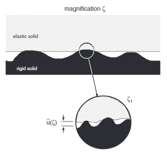
Fig. 3 Separation of the deformable (elastic) solid with the rigid surface u1(ζc) at magnification ζ.
The separation of the surface and the cup at this point is given by uc=u1(ζc) as shown in Figure 3. At further magnifications, more percolation channels appear, but these can be assumed to be smaller than the critical constriction. Therefore, their contribution to the leakage rate can be ignored for analysis, as the greatest contribution to leakage comes from the critical constriction. Leakage is assumed to happen only through the critical construction, which lets us approximate the total volume flow per unit time as
\begin{equation}
Q=M\Delta P
\end{equation}
\begin{equation}
M=\alpha\frac{u1^3(\zeta c)}{12\eta}
\end{equation}represents the viscosity of the fluid. To obtain these formulas, the laminar flow for water is assumed. In fluid mechanics, laminar flow fluid particles are considered to move along smooth paths in laminas or layers, where each layer slides smoothly over each adjacent layer (Streeter, 1998). Additionally, it is assumed that λc ≫ uc. ∆P is the difference between the outside pressure Pa and the inside pressure Pb and λc=L/ζc. The factor α is dependent on the exact shape of the critical construction. This first equation gives us an approximation for the flow rate for one of the square areas. Referring back to the diagram of the lattice in Figure 3, it is evident that there are N = Ly/Lx squares in total. Hence, the total leak rate for the entire surface is
\begin{equation}
Q=\frac{Ly}{Lx}M\Delta P
\end{equation}
This approximation is still incomplete as the separation u1ζc has yet to be found. Using percolation theory, the relative contact area A(ζ )/A0 was found to be approximately equal to 1 – pc, where pc is the aforementioned percolation threshold. The value of this threshold has been evaluated for hexagonal and square finite lattices, with values of 0.696 and 0.593, respectively. Taking pc ≃ 0.6, we get A(ζ )/A0 ≃ 0.4. The apparent relative area A(ζ )/A0, studying the system at different magnifications, can be obtained by:
\begin{equation}
\frac{A(\zeta)}{A_0}=\frac{1}{(\pi G)^{1/2}}\int_0^{p_0}d\sigma e^{-\sigma ^2/4G}=erf\left(\frac{P_o}{2G^{1/2}}\right)
\end{equation}
Where
\begin{equation}
G(\zeta)=\frac{\pi}{4}\left(\frac{E}{1-v}\right)^2\int_{q_0}^{\zeta q_0}dqq^3C(q)
\end{equation}
In this equation, E and v are the Young's elastic modulus and the Poisson ratio, respectively. Young's elastic modulus E is a measure of stiffness of a material (John, 1983). On the other hand, the Poisson ratio is the property of a material to expand or shrink in a direction perpendicular to a loading. The value of this mechanical property of a material usually varies between -1 and 0.5. Rubber-like materials have Poisson ratios closer to 0.5 (Gercek, 2007). u1(ζ) is defined as the average height separating the surfaces which appear to come in contact when ζ decreases from ζ to ζ-Δζ, where Δζ is a very small change in magnification. u1(ζ) can be calculated using
\begin{equation}
u1(\zeta)=\bar u(\zeta)+\bar u'(\zeta)A(\zeta)/A'(\zeta)
\end{equation}
In this case, ū(ζ) is the average interfacial separation.
Numerical methods for designing clingfish-inspired suction cups
Strain calculations
As seen from the formula presented above, Q = Ly/LxMΔP, with a higher pressure differential, leakage might increase. To counteract this effect, species such as the clingfish had to adapt specialized mechanisms to prevent leakage. A particularity in the geometry of the clingfish suction disc is the presence of “slits” between the pelvic fin and the posterior margin. Arita (1967) theorizes that this gap could decrease the performance of the suction cup, which was proven to be true in one specific case by Sandoval 2018. This is because the membrane that closes the gaps during adhesion could yield and break the seal. In fact, fishes that weren't able to close that gap were not able to adhere properly (Arita, 1967). Moreover, opening these gaps is a step towards terminating adhesion. However, Sandoval 2018 shows that there is only a decrease in adhesion strength on a convex surface whereas slits improve performance in the case of a concave surface. To understand this phenomenon, the effects of relief must be studied.
In order to create suction, a suction cup's margin has to stretch and adapt to the shape of the substrate. One way to improve the disc's compliance with the surface is to use a more flexible material, but this comes at a cost since the margin will be less able to resist slipping inward when a pull force is applied. However, Sandoval (2018) suggests that the slits provide reliefs that allow the margin to stretch more. Sandoval et al. (2019) expand on this subject by showing the effect that slits have on strain using finite element modeling (FEA).
To understand the usefulness of FEA for this kind of analysis and the effect of strain on the adhesion mechanism, one can first examine the case of a slit-less suction cup made of a single material as described in Tiwari & Persson (2019). In its initial state, which can be seen in Figure 4, the area of contact between the disc's margin and the substrate is 0.
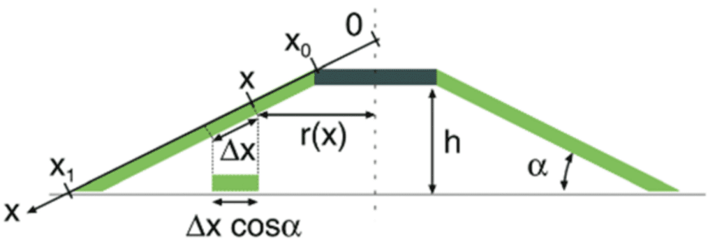
Fig. 4 Initial rest state of the suction cup (Tiware & Persson, 2019).
As seen in Figure 5, the force applied at the top of the suction chamber creates a displacement in the height of the top of the suction chamber. If the edge of the suction cup's margin is constrained in such a way that it does not slip outwards, this displacement causes radial compression in the disc's margin. As seen in Figure 5, a bit of length x will be compressed to a length ∆xcos(α) once the force F0 has sufficiently lowered the top of the suction chamber.
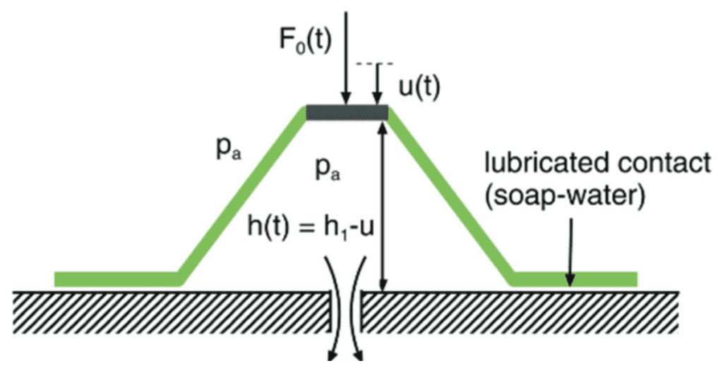
Fig. 5 Geometry of the suction cup when a force pushes down the top of the suction chamber by u and where the edges are constrained to the initial radius (Tiwari & Persson, 2019).
From the geometry, the strain ε can be rewritten to get
\begin{equation}
\epsilon=\frac{\Delta L}{L}=\frac{\Delta x-\Delta x\cos (\alpha)}{\Delta x}=1-\cos(\alpha)
\end{equation}
Because of perfect radial symmetry, the elastic energy was calculated as such
\begin{equation}
U=\frac{1}{2}VY\epsilon^2=\frac{1}{2}VY(1-\cos(\alpha))^2
\end{equation}
Where the volume V of the margin is given by
\begin{equation}
V=\int_{x_0}^{x_1}(2\pi x(\cos(\alpha))w(x)\;dx
\end{equation}
Where Y is the material's Young's modulus and V is the volume of the disc's margin. Suppose the thickness of the disc's margin decreases linearly from x0 to x; then the thickness w(x) can be expressed as w(x)=a+bx where
\begin{equation}
a=\frac{w_0x_1-w_1x_0}{x_1-x_0}
\end{equation}
And
\begin{equation}
b=\frac{w_1-w_0}{x_1-x_0}
\end{equation}
Consequently, the volume can be computed to be
\begin{equation}
V=2\pi\left[\frac{1}{2}a\left(x_1^2-x^2\right)+\frac{1}{3}b\left(x_1^3-x^3\right)\right]\cos(\alpha)
\end{equation}
If the potential energy is equal to the work required to compress the suction cup in the manner described above, the relationship between force and work gives this equation for F0
\begin{equation}
F_0=\frac{dU}{du}
\end{equation}
\begin{equation}
\frac{dU}{du}=\frac{d}{du}\left[\frac{1}{2}EV(1-\cos(\alpha))^2\right]=\frac{1}{2}E(1-\cos(\alpha))^2\frac{dV}{du}
\end{equation}Using the substitution u=(x1–x)sin(α), V is funda as a function of x and x is a function of u. Therefore, the chain rule gives
\begin{equation}
\frac{dV}{du}=\frac{dV}{dx}\cdot\frac{dx}{du}
\end{equation}
From the integral form of the volume equation, one obtains
\begin{equation}
\frac{dV}{dx}=2\pi x\cos(\alpha)w(x)
\end{equation}
Differentiating x with respect to u using the substitution gives
\begin{equation}
\frac{dx}{du}=-\frac{1}{\sin(\alpha)}
\end{equation}
Which leads to the equation
\begin{equation}
F_0=\pi[1-\cos(\alpha)]^2\frac{\cos(\alpha)}{\sin(\alpha)}Ew(x)
\end{equation}
This expression corresponds to the force required in the first step of adhesion, where the volume inside the suction chamber is reduced by lowering the top of the suction cup. This derivation shows that this force is proportional to the strain energy that would be stored when the suction cup is flattened. In other words, the force applies work that is then transformed into strain energy. However, the force is also responsible for applying work on the fluid to create a vacuum. This means that the work applied by a force is split between work done on fluids and potential energy stored in the suction cup. As a result, minimizing strain will improve performance for a fixed initial force that flattens the suction disc.
As shown above, an analytic approach can be taken in order to find the strain energy in a simple suction cup. However, it would be difficult to use a similar method in the case of one or more slits in the suction cup because the derivation assumes perfect radial symmetry and a constant margin radius over the whole disc. Therefore, another approach is required to quantify the reduction of strain energy that arises from the addition of slits. This can be done by computer simulation using finite element modeling. In FEM, a deformable object can be represented by a set of particles in the object's volume. When a force like the one that would flatten a suction cup is applied, these particles are displaced, and the difference between the final and initial positions of each particle creates a vector field. This vector field can then be used to calculate the strain and the elastic potential energy with tensor calculus.
Geometric characterization of clingfish papillae
The margin of a clingfish suction disc is covered in hexagonal pads called papillae. These structures have been theorized to contribute to adhesion performance by increasing the friction between the disc's margin and the surface it is trying to stick to. This is important because a vertical pull-off force will try to slide the margin inward, which would buckle the margin and break the seal. To better understand the role of the papillae, Sandoval et. al. (2020) characterize critical geometric features of the papillae to design similar structures in a biomimetic suction disc.
To do this, they first used frustrated total internal reflection (FTIR) to get images that can be processed manually and with automated software to extract the geometric characteristics of the papillae. Once they had the images, the first step was to do a manual binary conversion of the image to know exactly what pixels correspond to a point of contact between the margin's papillae and the substrate. They then used MATLAB to isolate and identify regions of interest with an area larger than 20px as papillae. Using the same set of tools, they found the aspect ratio of the smallest rectangle circumscribed about each papilla. The last automated step was to find the distance between the papillae by using the shortest distance between the regions of interest. Finally, they chose to manually determine the shape of the papillae because the edges were smoothed out during image processing.
The first finding was that the aspect ratio is independent of body size and was centered around 1.3 for all the specimens they studied. They also found that the elongation of the papillae increases when moving away from the center of the suction disc. Similarly, the probability distributions (Figure 6) of the area show that the papillae from the inner part tend to have larger surface areas. Lastly, they found an inverse relationship between the animal's size and the papillae's separation.
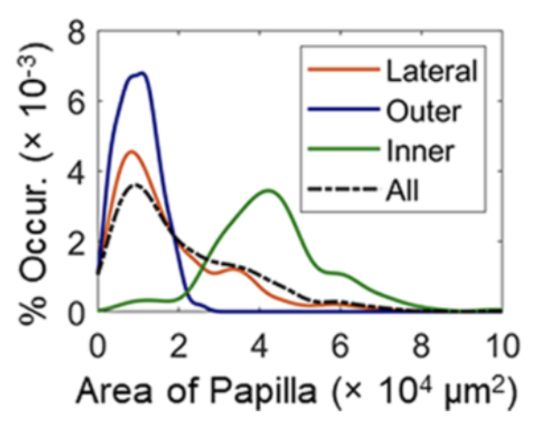
Fig. 6 Probability distributions for papillae area in different regions of the suction disc (Sandoval et al., 2020).
These results guided the design of surface patterns that try to replicate the effect of the papillae against shear forces. For this, they computed the average area of the papillae and made surfaces with structures that act like papillae. They then measured the shear stress when pulled on an acrylic surface lubricated with glycerol to observe the relationship between papillae separation and mucus. The results, as seen in Figure 7, show that the hexagons with the aspect ratio of natural papillae were nearly twice as good as the regular hexagons and squares. The authors also concluded that the separation between the papillae improves performance through fluid channeling, which helps Stefan adhesion. Moreover, the channels give geometric compliance to adapt to irregular surfaces.

Fig. 7 Stress results for different geometries (Sandoval et al., 2020).
Modeling octopus arm bend propagation and self-identification
As seen, different adaptations enhance the adhesion of the suction cups of species. How do other organs work in conjunction to control and utilize this mechanism? For this, an analysis of the arm of the octopus can help to illustrate this interaction. The neurobiology of the octopus has long been a subject of high interest for researchers seeking to understand the complex neural networks of intelligent invertebrates. Research shows that neural activity has evolved to display a vertebrate-like system that allows for lifelong neuroplasticity and learning capabilities (Hochner et al., 2006). Recent advancements in neurophysical resources for modeling brain activity, memory, and learning have allowed researchers to understand the neural activity of octopuses (Hochner et al., 2006). Octopuses have particularly complex and fascinating neurological systems, as shown by their ability to expertly maneuver their arms independently to capture prey, adjust the pitch of their suckers for optimal adhesion, and adapt quickly in new environments. In the following section, control of the octopus arms and suckers, key to the livelihood of the octopus, is explored at length.
Controlling the eight arms of the octopus poses a unique challenge since each of the arms has nearly infinite degrees of freedom in its movement (Nesher et al., 2014). In order to simplify control of the arms, the octopuses utilize a set number of movement patterns triggered by signals in the brain (Nesher et al., 2014). Wang et al. (2022) established a novel mathematical model for the movement of octopus arms and octopus suckers. In order to design a control law for bend propagation in octopus arms, the group modeled octopus arms as Kirchhoff rods, Cosserat rods (one-dimensional rod modeling bend, twist, shear, stretch) without stretch or shear. Bend propagation of the arm was modeled as a function of time t and arc length s. The centerline position vector is denoted r(s,t) and θ(s,t). Vectors e1 and e2 are the standard basis vectors of a two-dimensional analysis. Basis vector a = cosθe1 + sinθe2 = r is normal to the cross-section and basis vector b = -sinθe1 + cosθe2 forms an orthonormal basis with vector a. This variable definition is shown in Figure 8.
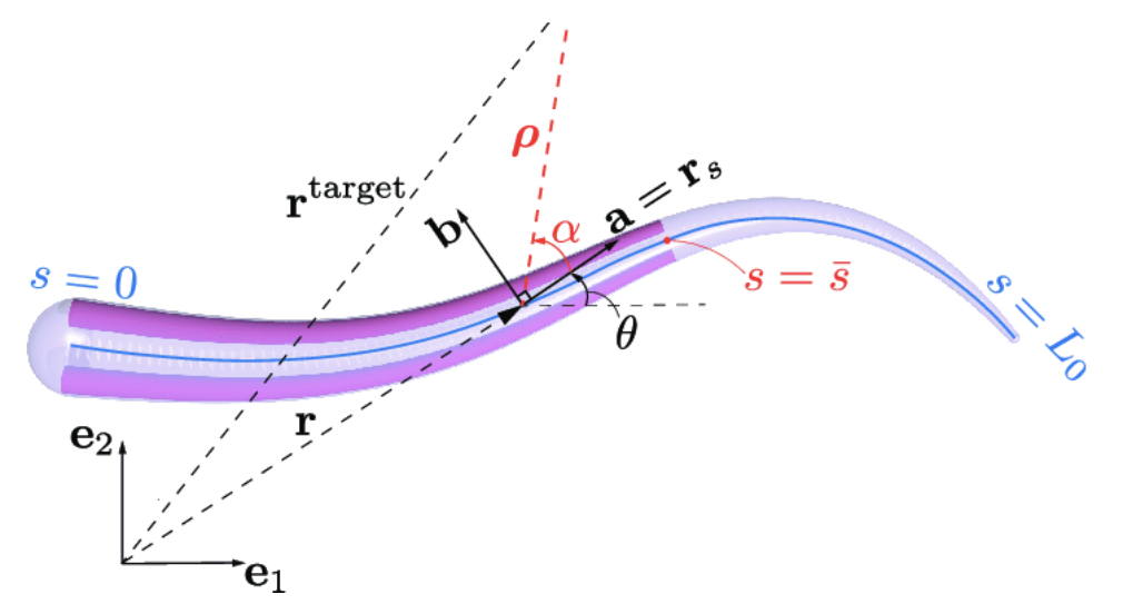
Fig. 8 Visual representation of variables associated with bend propagation in octopus arms (Wang et al., 2022).
Within the octopus arm are internal forces, n, and a couple moment, m. The couple moment, is dependent on the Young's modulus, E, and the second moment of area of the arm cross-section is defined as:
\begin{equation}
m=EI\theta
\end{equation}
The internal force, n, is defined as:
\begin{equation}
n=n_1a+n_2b
\end{equation}
The study established a system of partial differential equations for the arm movement:
\begin{equation}
(\rho Ar_t)_t=(Qn)_s-\zeta r_t+f_{drag}
\end{equation}
\begin{equation}
(\rho I\theta_t)_t=(EI\kappa)_s+n_2-\zeta r_t+f_{drag}
\end{equation}In the equations above, the study defined Q = [a b] as the planar rotation matrix, ρ as density, A as the cross-sectional area, and ζ as a damping coefficient.
The study proceeded to define a control law for the arm movement:
\begin{equation}
u(s,t)=-\mu(s,t)\sin(\alpha(s,t), \text{where } \mu(s,t)=\mu EI(s)
\end{equation}
Given a static target, the arm, according to the above control law, behaves as follows: given a straight arm with a static target just above the center of the arm and in reach of the arm when fully extended, the arm will propagate a bend from the center of the arm towards the target. The base of the arm bends sufficiently for the propagated wave to reach the target, at which point the arm falls back into its equilibrium position. Interestingly, the study concluded that any section of the arm past the point at which the arm will meet the target remains entirely inactive throughout the bend propagation.
Controlling eight arms simultaneously as independent appendages requires ensurement that each of its arms' movements do not interfere with movements of another arm. Behavioral experimentation on freshly amputated octopus arms, which retain full functionality for an hour post-amputation, show that the octopus is able to control its adhesion in order to inhibit this arm-arm interference (Nesher et al., 2014). Each of the octopus suckers has chemoreceptors that identify mucus on the skin of a live arm; when this chemoreceptor is activated, the suckers are deactivated. In order to demonstrate this, petri dishes were coated with a pure hexane solvent (control), hexane solvent + octopus skin extract, and hexane solvent + fish skin extract. The results are shown in Figure 9 below.

Fig. 9 Force readings of octopus suckers from freshly amputated arms on petri dishes coated with pure hexane solvent, hexane solvent + octopus skin extract, and hexane solvent + fish skin extract, respectively (Nesher et al., 2014).
The amputated arms adhered 10 times less strongly to the petri dish coated with octopus skin extract than to the petri dish coated with hexanes, and 20 times less strongly than to the dish coated with fish skin extract. Clearly, the suckers avoid binding with other octopus arms due to a self-recognition chemoreceptor interaction (Nesher et al., 2014).
Unraveling the complex octopus neurobiology reveals a feat of biological engineering. The self-identification of an octopus' own arms allows it to ensure that each arm does not interfere with the movement of another. The simplified control patterns used to manipulate the octopus arms allows the octopus to perform incredibly complex maneuvers in a short amount of time to efficiently capture prey at any distance and angle. Finally, the ability of the octopus to control each of its arms individually and the fact that the tip of the arm is inactive during prey capture allows the octopus to effectively maximize efficiency at the lowest energetic expense.
Octopus-inspired suction cups
Octopuses are one of the great organisms that can offer fresh ideas for creating robots useful in inspection and grasping in tight and unstructured environments. This is because, as shown previously, the octopus uses set patterns and chemoreceptors to control its suction cups. These creatures can also stretch, extend, and squeeze their entire body to fit through extremely small openings (Mazzolai et al., 2019). The following section covers two proposed designs of artificial octopus-inspired arms with suction cups. They have undergone numerous tests and yielded strong results, fueling the innovation of technological applications of suction cups.
In the first study conducted by Mazzolai et al. (2019), the soft arm's extended conical shape was created to ensure some degree of movement in small areas. To enable efficient twisting around items with a diameter of up to 30 mm, a length of 370 mm was chosen (based on the maximal diameter of the objects to be retrieved). Therefore, the maximum section obstruction, which ensures the spatial coexistence of the retrievable object and the soft arm in a 70 mm diameter environment, is a maximum diameter of 30 mm at the base of the arm and a minimum diameter of 4.5 mm at the distal side. The arm consists of an external softer cover and an internal stiff core. The rigid core serves as a backbone that acts like a spring to enable the arm to restore its shape after being actuated, while the soft cover ensures the necessary morphological adaptation to the object to be recovered. Three cables are utilized for actuation, and they are arranged in various ways, much like the muscle fibers of an octopus, to produce three distinct motions: dorsal bending, ventral bending, and twisting. Additionally, three fluidic channels have been built inside the arm core to power three different groups of suction cups. This process is summarized in Figure 10. At this point, silicone is injected into the mold to create the arm core (Mazzolai et al., 2019).

Fig. 10 Outline of the process of the creation and fusion of the soft arm and suckers (Mazzolai et al., 2019).
The suction cups contain a flexible stalk that functions like a spherical joint and a semicircular body to improve their capacity to adapt to irregular surfaces. According to their respective functionalities, three different types of suction cups were created, categorized, and integrated into the arm in three groups over the three fluidic channels. Using three different types of suction cups allowed the researchers to take the benefits of each type to maximize the function of the prototype. The first type was an open suction cup in which the external medium is immediately interfaced by the actuation channel that runs through the stalk. On the other hand, two other types of suction cups have a membrane separating the medium from the fluidic system. The second suction cup type consists of a flat membrane that shuts the cup and deforms when flow is engaged, allowing the suction cup to work. The third suction cup type has a concave membrane that clings to the semicircular body of the suction cup (with a little space between them) and allows passive attachment to an object in close proximity and controlled release when the fluidic channel is engaged (inflating the membrane). The three suction cup designs are illustrated in Figure 11, along with the overall arm prototype. With a lack of activation of the fluidic circuit, a preload between 0.5 and 1.0 N is sufficient to form an attachment (Mazzolai et al., 2019).
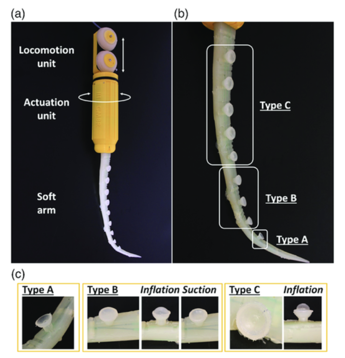
Fig. 11 Depicts the movement of the arm prototype a), as well as the design of each respective suction cup type (b and c) (Mazzolai et al., 2019).
Two main outcomes were attained. The first being strong grabbing forces, up to 3.6 N with a 30 mm cylindrical item, 2.3 N in water, and 1.3 N in oil. This increased the clutching force that the arm is capable of producing without suction activation: up to 2.7 N in air, 0.9 N in water, and 0.6 N in oil. These results are outlined in Figure 12. The second outcome was the ability of a greater variety of objects to be gripped due to the suction cups' presence, the arm's softness, and its inherent morphological adaptability. The prototype arm presented movement into 70 mm diameter pipes and proved sturdy in being able to adapt its configuration accordingly (Brown et al., 2010). The arm can manage three primary configurations – ventral, dorsal bending, and twisting – by regulating the three tendons separately, which mimic the longitudinal and oblique arrangement of muscles in octopuses. This increases the number of viable grabbing tactics. As for the three unique applied designs of suction cups, they each demonstrated adherence to extremely rough surfaces, and supported the grabbing task for many different geometries, ranging in forces (the threshold was maximum 2 N).
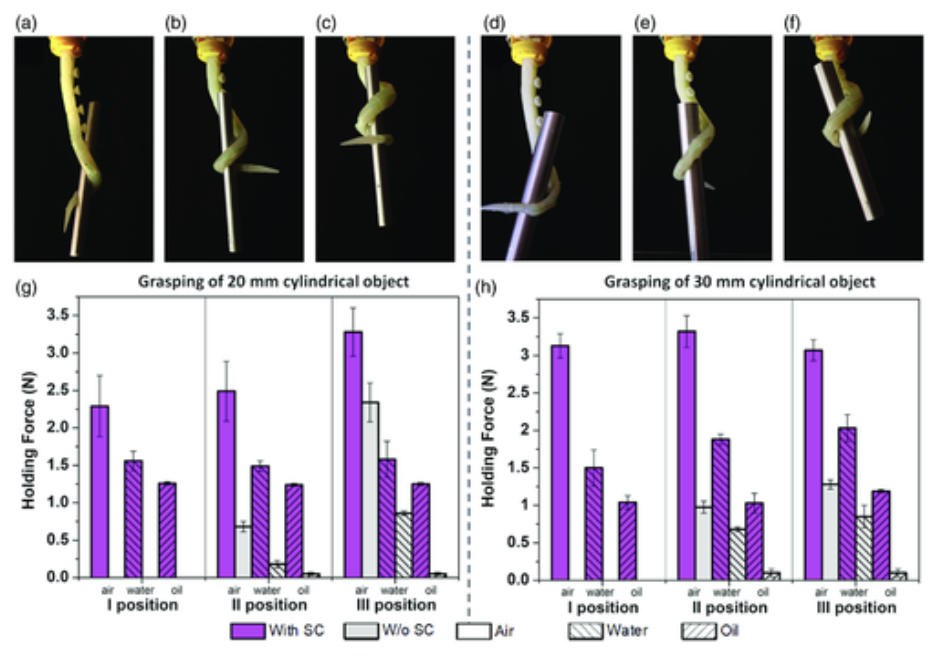
Fig. 12 Results of the three suction cups undergoing grasping tests (Mazzolai et al., 2019).
Overall, there were clear benefits and drawbacks of each type of suction cup had clear benefits and drawbacks. The first type was better at sustaining a grasp on an object; however, it proved less effective in dirty conditions. For the membrane-based cups, by filtering particles that may enter fluidic channels and acting concurrently, membrane-based cups can extend the lifetime of the system when operating in unclean fluids and can grab a variety of items (Mazzolai et al., 2019).
Without any prior knowledge of the sizes and shapes of the objects, the soft arm's adaptation and its interaction with the suction cups are crucial components for addressing non-standard recovery from wells, pipes, or tanks of a range of objects.
The second study by Tramacere et al. (2012) consisted of casting liquid silicone into a mold to generate artificial suction cups. This mold, assembled in resin, was inspired by the morphology of actual octopus suckers. It was composed of three components: two specular external elements, and an internal core (Tramacere et al., 2013). In order to simulate grooves on the surface of the infundibulum, the silicone forms a triangular shape. A had clear benefits and drawbacks multitude of surface geometries were generated, each uniquely characterized by width, radial distribution, and groove depth (Tramacere et al., 2015). These apparatus are shown in Figure 13.

Fig. 13 a) Resin (the three different components) mold that creates the suction cups, b) liquid silicone sealed after being poured, c) prototypes of suction cups before and after engraving, d) plexiglass used during engraving (Tramacere et al., 2015).
Using a pull-off setup, conveyed in Figure 14, the maximum force required to separate the suction cups from a Plexiglas substrate was evaluated to quantify the contribution of the surface features on the attachment performance of the suction cups. Each type of suction cup was put to the test by applying a range of pressures (0, 20, 50, and 90 kPa). The suction cups with smooth surfaces and the suction cups with engraved surfaces both displayed comparable mean detachment forces. From 0 kPa to 20 kPa, both smooth and engraved suction cups demonstrated a mean increase in detachment force that was, respectively, +100% and +145% for each type of suction cup. Higher pressure differential (at least 50 kPa) led to better performance for both the smooth and etched suction cups. The engraved suction cup with the greatest number of grooves (radial distribution of 1/18), greatest width of grooves (400 m), and smallest depth of grooves (100 m) demonstrated the best performance (with a percentage improvement of 65%) (Tramacere et al., 2015). The observed trend was that the attachment performance increased as the number, width, and depth of grooves increased. However, there was an abnormal result for suction cups that consisted of an in-between number of grooves. This behavior may be explained by the fact that, in suction cups with several grooves, a rise in groove depth corresponds to a rise in the volume of water residing beneath the grooves (Tramacere et al., 2015).

Fig. 14 Pull-off setup; a) is suctioning, b) is anchoring, and c) is pulling-off units (Tramacere et al., 2015).
These results show that the presence of bio-inspired grooves results in increased adhesive strength, deformability, and, therefore, toughness (energy required for detachment). Although different pressure differences were used during the testing, a discernible increase in detachment force was not seen for greater differences. We surmise that the lack of a similar increase was caused by air bubbles in the suctioning mechanism. In real-world circumstances, cavitation nuclei are frequently present and are indicated by air bubbles. Cavitation is a type of liquid fracture (in this instance, water) and would cause a saturation of the adhesive force comparable to a solid's saturation of strength. The saturation pressure difference, ΔPmax, where the saturation force is F~-ΔPmaxπR2, and R is the radius of the suction cup, can be estimated using Laplace's equation. By equating F~-ΔPmax=(2γ)/r, with γ being the liquid surface tension and r being the size of the cavitation bubble, r is roughly estimated to be 3.5 μm. Presuming that r holds an inverse relationship with R, F also holds an inverse relationship with R.
The suction cups with a borderline surface geometry, or those with the greatest number, width, and depth of grooves, produced the best performance (4.7 N, a 65% improvement over the smooth variant). With the exception of the groove width in the artificial suction cups, which is wider than that in natural suckers, this surface geometry is extremely close to the morphology of the octopus sucker (Tramacere et al., 2015).
Conclusion
In conclusion, mathematical analysis and modeling of the suction mechanisms of different species give us a deeper understanding of their functioning. Analysis of leakage in suction cups with percolation theory explains one of the main problems any adhesion mechanism encounters. Afterward, the different adaptations of the clingfish (slits and papillae) show how different species have evolved to diminish leakage and maximize adhesion. Fine element modeling and numerical approaches allowed the study of these adaptations. A geometrical representation of the octopus sucker and the theory behind chemoreceptors showed overall how specialized external mechanisms interact with suction cups and enhance the species' usage of suction cups. Finally, two different biomimetic adaptations exemplified the relevance of these mathematical analyses and further expanded on characteristics that increase the effectiveness of suction mechanisms.
References
- Beckert, M., Flammang, B. E., & Nadler, J. H.. (2016). A Model of Interfacial Permeability for Soft Seals in Marine-Organism, Suction-Based Adhesion. MRS Advances, 1(36), 2531–2543. https://doi.org/10.1557/adv.2016.445
- Bernardin, A.,(2021). Interactive Physically-based Simulation of the Suction Phenomenon. https://tel.archives-ouvertes.fr/tel-03258570/file/2021ISAR0001_BERNARDIN_Antonin_TheseDEF.pdf
- Brown, E., Rodenberg, N., Amend, J., Mozeika, A., Steltz, E., Zakin, M. R., Lipson, H., & Jaeger, H. M. (2010). Universal robotic gripper based on the jamming of granular material. Proceedings of the National Academy of Sciences, 107(44), 18809–18814. https://doi.org/10.1073/pnas.1003250107
- Gercek, H. (2007). Poisson's ratio values for rocks. International Journal of Rock Mechanics and Mining Sciences, 44(1), 1-13. https://doi.org/https://doi.org/10.1016/j.ijrmms.2006.04.011
- Hochner, B., Shomrat, T., & Fiorito, G. (2006). The octopus: a model for a comparative analysis of the evolution of learning and memory mechanisms. The Biological Bulletin, 210(3), 308-317. https://doi.org/10.2307/4134567
- John, V. B.. (1983). Elastic and Plastic Behaviour (pp. 73–100). https://doi.org/10.1007/978-1-349-17190-3_5
- Mazzolai, B., Mondini, A., Tramacere, F., Riccomi, G., Sadeghi, A., Giordano, G., Del Dottore, E., Scaccia, M., Zampato, M., & Carminati, S. (2019). Octopus‐Inspired Soft Arm with Suction Cups for Enhanced Grasping Tasks in Confined Environments. Advanced Intelligent Systems, 1(6), 1900041. https://doi.org/10.1002/aisy.201900041
- Nesher, N., Levy, G., Grasso, F. W., & Hochner, B. (2014). Self-recognition mechanism between skin and suckers prevents octopus arms from interfering with each other. Current biology, 24(11), 1271-1275. 10.1016/j.cub.2014.04.024
- Persson, B. N. J., & Yang, C. (2008). Theory of the leak-rate of seals. Journal of Physics: Condensed Matter, 20(31), 315011. https://doi.org/10.1088/0953-8984/20/31/315011
- Sandoval, J. A., Jadhav, S., Quan, H., Deheyn, D. D., & Tolley, M. T.. (2019). Reversible adhesion to rough surfaces both in and out of water, inspired by the clingfish suction disc. Bioinspiration & Biomimetics, 14(6), 066016. https://doi.org/10.1088/1748-3190/ab47d1
- Sandoval, J. A., Sommers, J., Peddireddy, K. R., Robertson-Anderson, R. M., Tolley, M. T., & Deheyn, D. D.. (2020). Toward Bioinspired Wet Adhesives: Lessons from Assessing Surface Structures of the Suction Disc of Intertidal Clingfish. ACS Applied Materials & Interfaces, 12(40), 45460–45475. https://doi.org/10.1021/acsami.0c10749
- Streeter, V. L., Wylie, E. B., & Bedford, K. W. (1998). Fluid mechanics (9th ed.). WCB/McGraw Hill. https://lccn.loc.gov/97036324
- Tiwari, A., & Persson, B. N. J.. (2019). Physics of suction cups. Soft Matter, 15(46), 9482–9499. https://doi.org/10.1039/c9sm01679a
- Tramacere, F., Beccai, L., & Mazzolai, B. (2013, May 31). What Can We Learn from the Octopus? Pubs.rsc.org. https://pubs.rsc.org/en/content/chapter/9781849737135-00089/978-1-84973-713-5
- Tramacere, F., Beccai, L., Mattioli, F., Sinibaldi, E., & Mazzolai, B. (2012, May 1). Artificial adhesion mechanisms inspired by octopus suckers. IEEE Xplore. https://doi.org/10.1109/ICRA.2012.6225058
- Tramacere, F., Follador, M., Pugno, N. M., & Mazzolai, B. (2015). Octopus-like suction cups: from natural to artificial solutions. Bioinspiration & Biomimetics, 10(3), 035004. https://doi.org/10.1088/1748-3190/10/3/035004
- Wang, T., Halder, U., Gribkova, E., Gillette, R., Gazzola, M., & Mehta, P. (2022). A Sensory Feedback Control Law for Octopus Arm Movements. https://doi.org/10.48550/arXiv.2204.00717