


Abstract
Many organisms possess internal defense mechanisms, intrinsic properties, and behaviors adapted for their survival. Spines and quills differ immensely across families, and this disparity exacerbates further amongst taxa. Environmental pressures such as predation and habitat unique to each species results in various physical design mechanisms for spines and quills. Yet despite these differing properties and functions, animal species’ spines have still developed similar purposes. Across phylum and orders, spines share functionality and mechanisms. There are numerous distinctions and parallels between spine and quill structures across a wide array of organisms. More specifically, this essay delves into the spines and quills of various organisms and their mechanistic utilization for self-preservation.
Introduction
Spines are found on a variety of organisms, on both plants and animals alike. They are essential tools that assist animals, like porcupines, to survive in environments with apex predators. Similarly, plants use their spines to ward off predators, but they also have configured their microstructures to enhance their ability to collect environmental resources. When examining porcupine spines, their compressibility and detachment from the animal allow for optimal protection in their harsh environments. The spines of a hedgehog are not designed for removal like those of a porcupine. Hedgehog spines embedded themselves within the skin, such that it has been said that a hedgehog can be picked up by a single spine (Vincent, 2002). Porcupine spines are designed to deter predators, and they become erect when the animal experiences a threat, and the quills can detach to impale attackers. These spine varieties contain keratin, a protein found in hair, fur, hooves, and horns. The spines of Cacti contain the structurally-strengthening protein lignin. In contrast to mammalian spines, cacti spines have adapted the shape of their spines to accumulate water; the increase in spine radius towards the cacti evolved to funnel condensed water towards the plant. Spines can also be found in aquatic environments, as sea urchins possess spines crucial for marine survival. Sea urchins may appear simple since they are just a sphere with spikes protruding outwards, but through a microscopic lens, those protruding spikes reveal a highly complex, porous microstructure that fulfills several functions simultaneously. Due to that structure, a sea urchin’s spine can be highly durable, flexible, and resistant to crushing and twisting forces almost entirely. The spines and quills of the mentioned organisms will be examined through their structural composition, functionality, physical attributes, and their applications to their environment. This paper aims to quantify the plethora of spines in the natural world and the commonalities and variances between them.
Porcupine quills
A creature frequently associated with spines is a porcupine. Despite the popular belief that porcupines can project their spines, the true purpose of a porcupine’s quills is self-defense. Rather than projecting their spines, porcupines fling their bodies around and swing their tails to defend themselves from predators. Their quills can then detach with minimal resistance, and as a result, predators who encounter porcupines often leave with no meal and quills stuck in their snouts and paws.
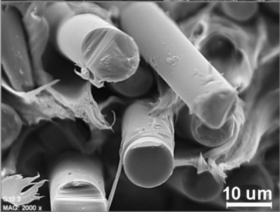
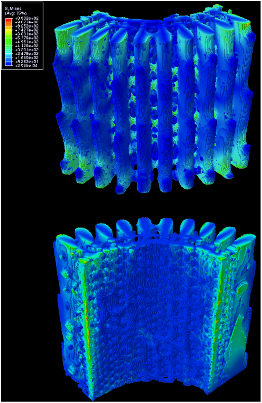
Their quills are incredibly effective at inflicting damage upon predators. The black-tipped conical section at the top of the quill (Figure 1) is covered by minuscule barbs, which require a much larger force to remove the quill (Cho et al., 2012). The sharp conical structure (Figure 1A) facilitates penetration, and the wedges (Figure 1B) create significant difficulties in removing the entire quill. This can vary even across species, as seen by the African Porcupine, which does not possess these barbed quills.
Fig. 1 (A) North American porcupine quill. (B and C) FE-SEM images show the microstructure of the quill tip and base, respectively (Cho et a.l, 2012).
Additionally, quills with barbs have a higher penetration force (Figure 2, Figure 3); they penetrate deeper than quills without barbs when the same force is applied. Quills penetrate tissue by deforming them until they reach a critical point when a crack is formed, and then the quill penetrates, spreading the crack, similar to how needles function (Sherlgold & Fleck, 2004; Das & Ghatak, 2011).

Fig. 2 A) FE-SEM image showing the microstructure of the tip of the porcupine quill. (B) Representative force versus extension plots shows puncture, penetration, and removal of barbed, barbless, and African porcupine quills from muscle tissue. (Inset) Micron-level topography of the three quills. (Scale bars: 100 μm) Red arrows indicate resistance as the barbed quill is removed from the tissue (not observed for others) (Cho et al., 2012).
The barbs on the quills act like serrations on a knife (Anderson & LaBarbera, 2008). They cause the tissue to fail with a lower input of force (Cho et al., 2012). When we think of cutting bread, we choose a bread knife (with large serrations) rather than a butter knife (with small serrations) since it provides smoother cuts. Similarly, barbed quills penetrate tissue (Figure 5) more easily than smooth quills and produce smoother cuts (Figure 4A).
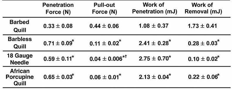
Fig. 3 Summary of experimental values obtained from penetration and removal of a barbed quill, barbless quill, 18 gauge needle, and African porcupine quill (mean ± SD, n = 5). Each mean is compared with every other mean using one-way ANOVA with Tukey’s Honestly Significant Difference post hoc analysis to correct multiple comparisons at a 95% confidence interval by using GraphPad Prism 6 (*P < 0.05, compared with a barbed quill; †P < 0.05, compared with a barbless quill) (Cho et al., 2012).
It is thought that since these barbs are roughly the same size (50-100 µm), they can cause local stress concentrations, which facilitate penetration into the tissue (Maier & Bornemann, 1999; Cho et al., 2012). Upon entry, the quills are compressed along the axis, reducing tissue entry at all points along the barbed quill. From a physical perspective, these barbs act like the speed flaps on the wing of an airplane. They remain attached to the main structure since they do not want to create resistance to the movement of the main object (the plane or the quill). In airplanes this shape provides a smooth cut through the air to reduce drag while increasing lift. The similar design of the barbed quills allows for reduced force upon penetration, and the barbs will enable the quill to cut through tissue more easily. Upon removal, these barbs also have an opposite force since they are no longer static on the quill axis.
Fig. 4 Barbs reduce tissue damage and facilitate penetration into tissue. (A, B) Representative histological images of tissue samples penetrated with barbed and barbless quills, respectively, showed significantly less damage induced by the barbed quills (n = 5). (Scale bar: 200 μm.) (C and D) Microcomputed tomography (Micro-CT) images present the penetrated barbed (C) and barbless (D) quills within tissue. Both quills were penetrated into tissue with an applied force of 0.2 N. The red dashed arrows indicate the penetrating depth of the quill. (Scale bar: 1 mm) (E) Mean penetrating depth of barbed and barbless quills observed in micro-CT images (n = 3) (Cho et al., 2012).
When pointy quills are barbed, they require substantially more force to pull out (Cho et al., 2012). The quills pictured below (Figure 5) are synthetically made; however, they illustrate the same point as natural barbed porcupine quills. In comparison to other engineering structures, these provide a sort of drag force, much like speed brakes on airplane wings or normal forces caused by the hooks of grappling hooks. These micro barbs provide significant adherent forces to the tissue. They require significantly more force to be removed (Figure 5B, 5C).
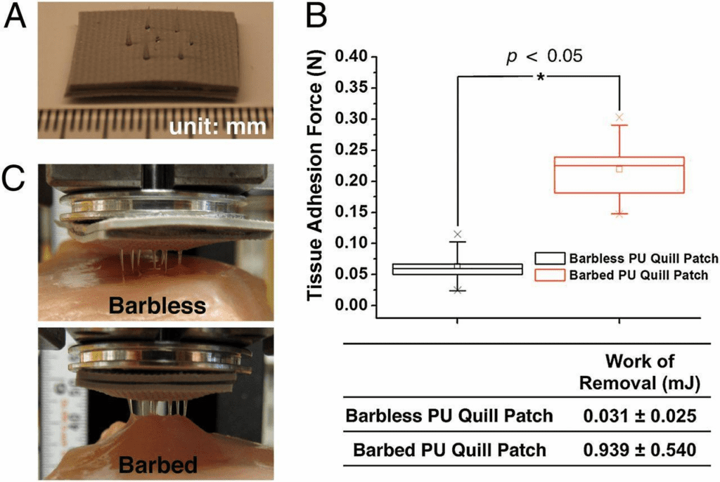
Fig. 5 A prototypic quill-mimetic patch as a mechanically interlocking tissue adhesive. (A) The digital photograph shows the fabricated quill-mimetic patch, which consists of 7 PU barbless or barbed quills. (B) The tissue adhesion forces were obtained from barbless and barbed PU quill patches (n = 5, Student t-test at the level of 95% significance). The box plot whiskers are set to ±1.2 SD. The two “X”s in the box plot indicate the first and 99th percentiles. (C) Shows the quill-mimetic patches interacting with muscle tissue during the retraction process from muscle tissue (Cho et al., 2012).
Most significantly, porcupine quills are very effective at piercing and remaining embedded in their predators. The question arises, how do porcupines release their quills, and how does this mechanism work, so that the porcupine can safely escape instead of remaining attached to the predator by its quills?
These quills become erect (Figure 6A, 6B), particularly when the porcupine’s defense mechanism is activated. This is made possible by the piloerector muscle at the base of each quill. When the quill comes in contact with an external force, the quill is deflected, breaks the epidermis, and then travels back slightly. This back travel weakens the contact between the quill follicle and surrounding tissues, allowing for smoother removal of the entire quill (Figure 6). This is an important evolutionary development for the porcupine. The removal of the whole quill ensures the porcupine does not remain attached via its quills to a predator, nor does it require a force so large that it would snap the quill before it is removed.
The release mechanism of the quill achieves its purpose as a defense mechanism by not attaching itself to predators, and not piercing itself. Otherwise, this would act as a double-edged sword, ensuring damage to the predator at the cost of damage to itself or increased danger by remaining attached to the predator. Compared to other animals that release their spines, like honeybees, porcupines do so at a relatively low cost to themselves. Their quills regenerate quite often, and when their spines are released, they do not also lose important body parts, like a honeybee would, which could cost them their survival.

Fig. 6 Proposed mechanism for facilitated quill release, showing differences between erect and relaxed quills. Abbreviations: e = epidermis; p = piloerector muscle; q = quill base; r = retinaculum; s = spool; t = transverse muscle. A) Erect quill in aroused porcupine, with transverse and piloerector muscles contracted. B) Erect quill has traveled deeper into the skin after striking an object and moving through an immobilized spool, with quill root shearing attachment to surrounding tissue. C) Relaxed quill in anesthetized porcupine, with transverse and piloerector muscles relaxed. D) Relaxed quill has struck an object. The spool and surrounding tissues have traveled with the quill root, preventing the shear of the root attachment. Arrow indicates the direction of impact on the quill (Roze, 2002).
Additionally to this self-preservation mechanism, the internal physical design of porcupine spines provides protection from force impacts. Porcupine spines have similar microstructures to foam. This allows them to have Young’s Modulus of roughly 6.0 GPa, which is stronger than most synthetic materials. Nylon, a compound used extensively in fabrics and plastics, has a Young’s Modulus near 2000 MPa, which is significantly less than that of a porcupine quill (Piccinini et al., 2011). Given the foam-like structure of porcupine quills (Figure 7a) it is particularly interesting that they have such a high Young’s Modulus. The quill is particularly strong because it contains internal stiffening ridges in the longitudinal direction (Vincent & Owers, 1986). Compared to beams or other structures which have to support large loads, the internal structure of the quill is beam filled. The stiffening ridges (Figure 1a) provide a large load support to the quill. When there is a load on top of the structure, the forces get dispersed along all the longitudinal stiffeners across the length of the quill. Since there are stiffeners all around the structure, and it is shaped like a circle, it acts like a column with many longitudinal beams that cross the beam. This gives the structure great resistance to loads, and is part of why the quill has such a high Young’s Modulus. The high Young’s Modulus is due to the apparent modulus of the structure rather than just the foam-like properties of the quill. Collectively, this creates a great resistance to loads from all directions.
One deficient characteristic of porcupine spines, is that compared to other species, porcupine quills have a lower resistance to buckling. Buckling does not happen often, since their quills can easily detach from the dorsal area of the porcupines, and do not damage the porcupine. The foam-like internal structure of porcupine quills provides a significant contribution to delaying the onset of buckling (Jensen et al., 2020). Since the quills are never struck from a completely vertical angle, the force will not be distributed equally along the longitudinal stiffeners. This increases the chances that the quill, particularly the stiffeners, will buckle since the load cannot be distributed as evenly to the other “beams” (the stiffeners) in the quill. As humidity increases, the resistance to force of these quills decreases (Chou & Overfelt, 2011). In comparison to cylindrical pieces of foam, it makes sense that quills are weaker when wet. Much like a cardboard tube, it loses rigidity and its ability to resist force when saturated with water. Porcupine spines are like cylindrical shells filled with foam (Fig7a-i). Internally, these resemble the foam and cylinder shape of grass, hedgehogs, and sea urchins (Karam & Gibson, 1994).


Fig. 7 Three-dimensional view and surface morphology of porcupine quill. (a) whole quill before compression. (b) cross-section of the whole quill, (c) vertical cross-section of the whole quill, (d) shell, and (e) foam after compression. (f, g) SEM images of the horizontal cross-section of the quill before compression. (h, i) SEM images of a vertical cross-section of quill after compression (Tee et al., 2021).
Hedgehog Spines
Unlike porcupines, hedgehogs cannot release their spines to defend themselves. Their spines are barbless and relatively short (2-3 cm) compared to North American porcupine quills (4-5 cm) (Chou & Overfelt, 2011). Thus, the defense mechanism of hedgehogs differs from the defense mechanism of porcupines. While porcupines can detach their quills to let them penetrate the skin of the predator, hedgehogs can only roll into a ball. This leads to the contraction of dorsal muscles, which make the spines on the back of the animal stand up, but not fall off. Hence, most predators will run away (Swift et al., 2016).
The mechanism behind the erection of the spines is similar to the standing of a hair. A muscle is located at the base of each spine and can contract to make the spine stand up. When the muscle is relaxed, the spine stays flat on the body (Mori & O’Brien, 1997).
Other than defense, their spines serve another important function. They can protect the animal from injury when it falls from heights. Hedgehogs often climb trees to fetch insects and can jump from heights to escape predators without being hurt (Swift et al., 2016). This can be explained by the high shock-absorbing capabilities of their spines.
The internal structure of hedgehog spines is unique and plays an important role in absorbing impact energy (Li et al., 2022). As shown in Figures 8 and 9, spines contain transverse and longitudinal elements. Transverse diaphragms, or septa, form close cellular structures equally distributed inside the spine, providing rigidity, while longitudinal stringers enhance flexural stiffness (Drol et al., 2019).

Fig. 8 Representation of a hedgehog spine. The 2 main components are the longitudinal stiffener and the septum, also called, the transverse diaphragm (Vincent & Owers, 1986).

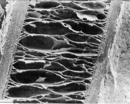
Fig. 9 Internal structure of hedgehog and tenrec spine. The two images (a) and (b) above represent the longitudinal section and transverse section of a hedgehog spine. The image below (a) and (b) corresponds to the internal morphology of a tenrec spine. The distance between the septa is much smaller in the case of a tenrec spine (Vincent & Owers, 1986).
To thoroughly understand the mechanism behind the shock-absorbing capability of the spines, it is important to discuss the concept of buckling. A structure under a load can be suddenly deformed or start bending. However, it will only start to change shape or buckle when this force exceeds a certain value called Euler’s critical load (Maxfield, 2009). The Euler formula used to calculate the critical buckling load (P) is given by:
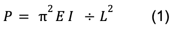
E represents Young’s modulus, I corresponds to the second moment of inertia and L represents the length of the column (Maxfield, 2009).
In this equation, the Young modulus depends on the material of the column, which is keratin in the case of a hedgehog spine (Vincent & Owers, 1986). Moreover, this formula shows that the length affects the maximal force that can be applied. By decreasing the length of a column, the critical load is increased. In a hedgehog spine, the length is relatively short compared to quills from porcupines. Hence, the critical load is high, and the hedgehog spine can bear a greater load than the porcupine quill before failing.
When hedgehogs fall and impact the ground, a longitudinal force is exerted on the spine. According to Euler buckling, the spine will start to buckle only if the force exceeds the critical load, as presented in Figure 10 (Vincent & Owers, 1986).
Fig. 10 Buckling of a spine. The spine starts to bend when the force exceeds Euler’s critical load (Vincent & Owers, 1986).
The morphology of the spine, particularly in the transverse septa, delays buckling. Those diaphragms maintain a high second moment, allowing the spine to resist the load. Thus, they prevent the ellipticity of the spine (Li et al., 2022). Also, those spines can support 200 times the critical load before deforming permanently. The internal structures are highly resistant to buckling since they can absorb large amounts of energy before failing. This elastic energy will be stored in the spine and is released after the impact. The spine then returns to its original shape. This explains why hedgehogs can fall at a speed of 15 m/s without having their spines broken or deformed (Swift et al., 2016). The spine can also deform permanently if it absorbs too much energy, but this will only happen in extreme conditions. In this case, it will adopt an oval shape. It is called the Brazier effect, as shown in Figure 11 below. It has been shown that the transverse diaphragms play an essential role in resisting tensile load and keeping the cylindrical shape of the spine (Vincent, 2002). Tensile stress is the resistance of an object to a force that could tear it apart. It is dependent on the force being applied divided by the cross-sectional area. So when the cross-sectional area is reduced with the same amount of force being applied, the result is a higher tensile strength. The transverse diaphragms allow for the cross-sectional area to be much smaller than otherwise expected since they provide additional support, and rigidity to the structure. These essential structures allow the tensile strength to be high, producing an increased resistance to any tear that could occur from local buckling.

Fig. 11 Buckling causes an ovalization of the central section of a hedgehog spine (Vincent, 2002).
There is also uniformity in the spines on the back of hedgehogs. It can be explained by the fact that all the spines should absorb the same amount of impact energy since the main function of a spine is to absorb energy to prevent deformation. This way, no matter how the animal falls, on the side or its back, the spines will have the same shock-absorbing ability, protecting the animal from injury. By comparison, the quills of porcupines vary in terms of length, diameter and shape and fail easily (Vincent & Owers, 1986).
Many engineers think that understanding the mechanism behind the hedgehog spine’s shock-absorbing properties could assist the development of lightweight and impact-resistant structures. The internal structure of hedgehog spines, and particularly the evenly distributed septa, allow the spine to have both high flexural strength and low weight, which is often an issue in the design of structures. Interestingly, a company is currently developing a football helmet liner inspired by a hedgehog spines structure (Drol et al., 2019).
Sea Urchins
In contrast to other land animals, sea animals have also adopted spines as reasons for self-defense, and movement. Sea urchins (Echinoidea) commonly populate marine beds. However, unlike other sea animals, they cannot swim and have a quasi-total reliance on their spines for self-defense and motion.
Sea urchins are often found in rocky areas (Figure 12), where they are subject to thrashing waves and currents which throw them repeatedly against rocks. For this reason, their spines must be able to handle various strains and physical forces in various ways such as to limit the damage applied to the central structure of the sea urchin. Sea urchins’ spines provide resistance to various forces due to evolutionary pressures to survive in harsh environments. The spines are often used like sacrificial limbs that absorb the energy from a physical shock.
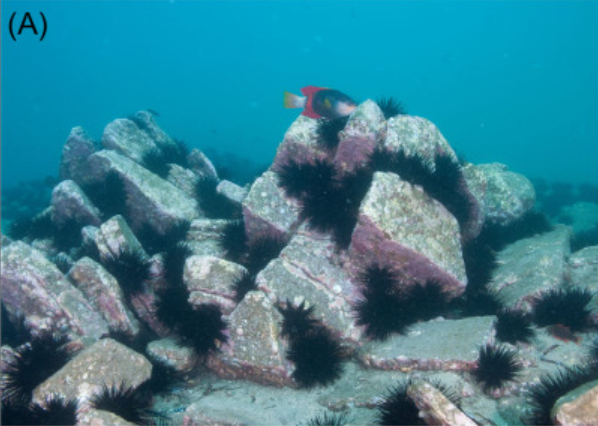
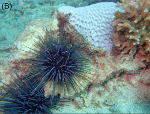
Fig. 12 Centrostephanus rodgersii sea urchins in their natural habitat (Byrne & Neil, 2020).
Structure of the Hollow Spine
Generally speaking, the spine of a sea urchin varies between two categories; the Clypeasteroida and the Camarodont. The difference is that the former grows hollow spines while the latter grows full spines. The following will entirely focus on the Clypeasteroida variant to analyze the porous structure of their spines (Tsafnat et al., 2012).
By looking at a sea urchin from the Centrostephanus rodgersii family as a model, one can see that its spine, similar to almost all other sea urchin species, has a cone-like shape. The Centrostephanus rodgersii’s spine has a base diameter of 4 mm while its tip has a diameter of 1 mm, thus giving it its needle-like constitution (Tsafnat et al., 2012). Interestingly though, the interior of the spine is hollowed out due to the central hole in the spine, and the remaining volume is then covered full of pores (Figure 13). As a result, these spines manage to be extremely light due to their low mass relative to their volume.

Fig. 13 Microscopic view of the Centrostephanus rodgersii’s spine. A illustrates the central hole inside the spine. B shows the stacks of barbs that form the lateral surface (Tsafnat et al., 2012).
Figure 14 below illustrates the inner and outer structure of the Centrostephanus rodgersii’s spine. Starting from the outside, the lateral surface of the spine is covered with microscopic barbs that point towards the tip (Figure 14), as opposed to the porcupine’s quill barbs that are oriented downwards. The microscopic barbs are all part of a vertical column, and the whole spine is formed by many columns of barbs extending upwards. These columns, or blades, are called wedges (Figure 14), and, viewed from the outside, they are noticeable when looking at the gap between each barb. However, the whole structure of the wedge extends from the outer surface of the spine into the middle interior of the spine. While seemingly insignificant, they play a crucial role in the spine’s capacity to resist breaking forces. The spine of the sea urchin constructs its outer layer by circularly stacking all of these wedges, and to connect all of them, these long columns are connected with what is referred to as bridges (Figure 14). Bridges are made of the same calcite mineral as the barbs, and they protrude outwards to connect to the next column (Tsafnat et al., 2012). As a result, every blade is held together tightly by hundreds of branches from the base to the tip.

Fig. 14 Micro-computed tomography image of a section of the Centrostephanus rodgersii’s spine. 1: Inner Wall, 2: Wedge, 3: Microscopic Barb, 4: Bridges, 5: Porous Zone (Tsafnat et al., 2012).
The second to last layer is the porous zone. Although it appears to be an extra padding zone to resist more crushing strength, it actually fulfills that function while saving as much weight as possible (Tsafnat et al., 2012). The backbone of the entire spine is located at the very center, called the inner wall.
Viewed from above, one can perceive the bridges by looking at the space between the diamond-shaped wedges (Figure 15, Figure 16). A small branch joins one diamond-shaped wedge to the next.

Fig. 15 Cross-sectional view of the Centrostephanus rodgersii’s spine from above (Tsafnat et al., 2012).
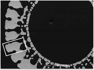
Fig. 16 Cross-sectional view of the Centrostephanus rodgersii’s spine from above. The white rectangle isolates a single wedge (Tsafnat et al., 2012).
Effects of Compressive and Tensile Stress
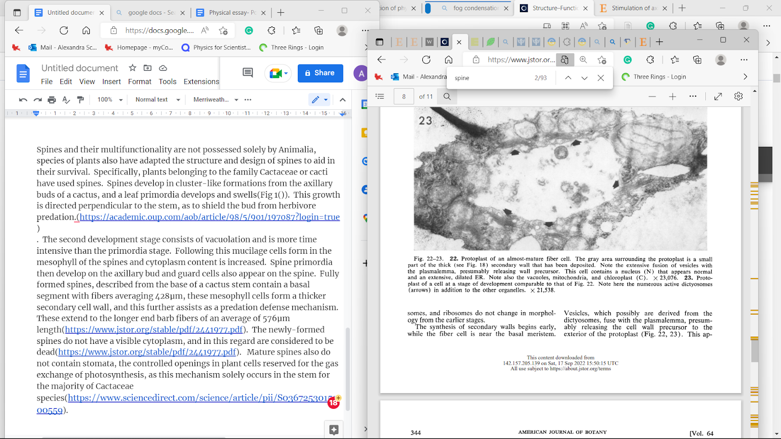
As mentioned previously, the wedges are crucial in helping the spines resist breaking due to stress. Figures 17-18 below display the amount of stress each section of the spine undergoes during tension and compression. When the spine is forcefully stretched or compressed by 1% of its total length, most of the stress is spread into the wedges of the spine. Following the data below, the space between the barbs, or the outer part of wedges (Figure 17), receives the most stress. Moreover, the internal structure of the wedges (Figure 18) also experiences a substantial amount of stress. Due to this distribution, the porous zone and the center of the spine remain unharmed. There are two properties of the wedge that cause this phenomenon. Firstly, the wedge’s internal structure is similar to that of glassy material (Figure 19) (Tsafnat et al., 2012). Consequently, the wedges share a similar compressive strength with glass, and it is responsible for most of the spine’s durability. Compressive stress originates from forces being applied on an object, in such a manner that they aim to reduce the volume of the object. These forces can be seen as those acting on an object crushed with a hydraulic press. These forces often lead to buckling of the object, so if the object has a high compressive force, it will not buckle under external forces as easily. Secondly, the fact that wedges are the only major component of the spine that does not contain any holes, excluding the barbs, means that most of the spine’s mass is located in that section. As a result, the brunt force of a collision will mostly spread to the wedges (Tsafnat et al., 2012).
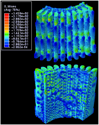
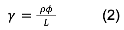
Fig. 17 Distribution of von Mises stress along the length of the spine under 1% compressive strain, All values in the legend are in MPa. The top 3D object is the outer surface of the spine, while the bottom 3D object is the inner surface of the spine (Tsafnat et al., 2012).
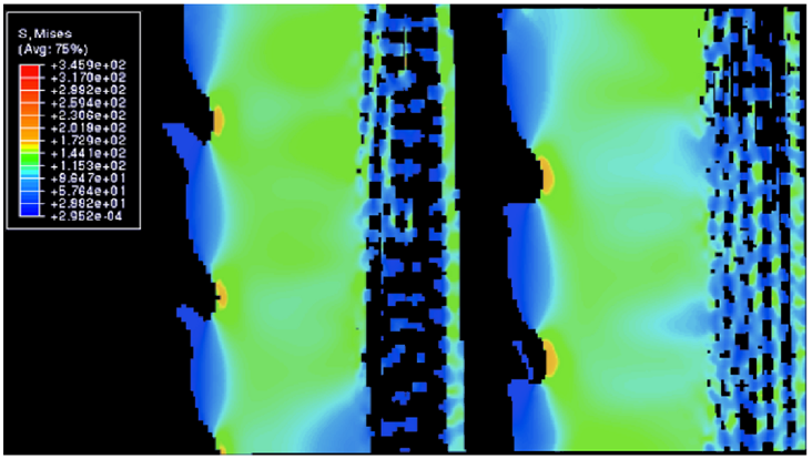
Fig. 18 Cross-sectional view in between a single wedge. All values in the legend are in MPa. The protruding branches are the microscopic barbs, while the section highlighted in light green shows the whole wedge. The zone to the right of that is the porous zone. Notice how most of the stress is distributed into the wedge, or the outer layer of the wedge between the barbs where the stress is at its highest (Tsafnat et al., 2012).

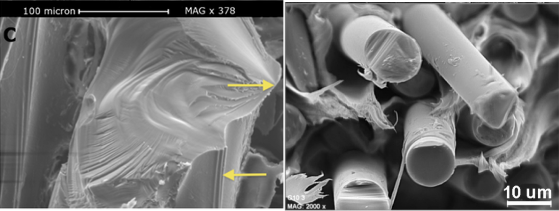
Fig. 19 The left image is a fracture on the Centrostephanus rodgersii’s spine’s wedge (Tsafnat et al., 2012). The top arrow points to the fracture origin. The right image illustrates the cross-sectional area of broken glass fibers (Gómez et al., 2021). Notice the similarity between the two despite the fact that one is made naturally, while the other is synthetic.
As an additional defense against crushing forces, an ingenious yet naturally-developed, fail-safe mechanism is installed into the bridges. Since bridges are hundreds of tiny branches, if one wedge were to undergo a large amount of stress, then the adjacent bridges would fracture, thus halting the spread of cracks into other wedges (Tsafnat et al., 2012). A safety mechanism like this could not happen if the spine was simply covered by a single wedge instead of a whole stack of them.
Sea Urchin Inspired Concrete Designs
Scientists have developed a special type of concrete called “Functionally Graded Concrete,” or FGC, based on the Heterocentrotus Mammillatus, a hollow-spined sea urchin. The main motivation for doing so was the drastic reduction in density, and subsequently in weight, at a relatively low cost in durability. The density of normal, solid, concrete is around 2160 kg/mᶟ, while that of this porous variant is around 1300 kg/mᶟ (Toader et al., 2017).
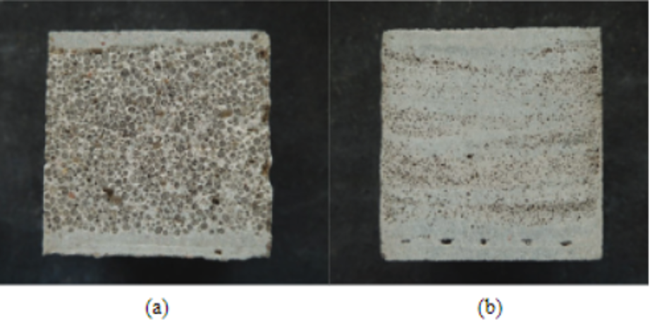
Fig. 20 Samples of porous concrete. The concrete (a) was made by casting while the one in (b) was made by spraying. Both slabs contain expanded glass bubbles, spheres of brown color of varying sizes, to simulate the empty pockets of the porous structure of the Heterocentrotus mammillatus (Toader et al, 2017). Casting concrete involves pouring liquid concrete into a container of a specific shape and waiting for it to solidify (a). Spraying concrete involves spraying liquid concrete and having it aggregate until a pile is formed (b). If one were to assume that normal concrete has a maximum density of 2160 kg/mᶟ, then cast and sprayed concrete possess 45% and 71%, respectively (Toader et al., 2017).
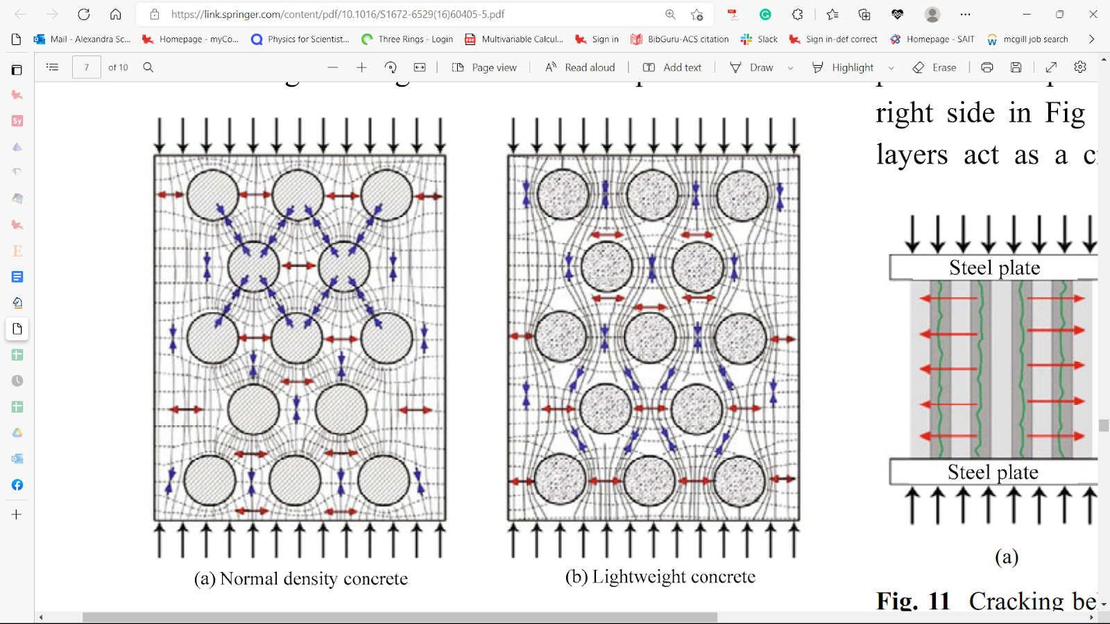
Instead of purely using porous concrete, scientists constructed structures using a mix of porous and solid materials just like how the sea urchin’s spine possesses a solid wedge amidst the remaining porous structure. By inducing gradually increasing compressive forces, they noticed that since the lightweight concrete has a lower density, most of the compressive force passes through the cement paste instead of the porous aggregates. This causes most of the force to be distributed into the cement paste, while avoiding the aggregate grains (Figure 21), similar to how wedges take the brunt of the force in spines (Toader et al., 2017). As a result of being squeezed shorter, the slab of concrete becomes wider, thus creating a tensile stress perpendicular to the compressive force (Figure 21) (Toader et al., 2017). Consequently, a weak aggregate interacts with the tensile stress only. For this reason, the tensile strength of lightweight concrete is almost entirely dependent on the aggregate’s strength, since it is the weakest link in the concrete slab (Toader et al., 2017).

Fig. 21 Major stress trajectories inside regular density concrete (a) and lightweight concrete (b) under compressive forces. Notice how in normal concrete, the compressive force bounces from one grain to another, as seen from the blue arrows moving to another circle. In (b), the compressive force follows the flow of the cement paste instead since the aggregates are far lighter. However, as the slab is squeezed shorter, it’ll be pushed wider in response. The red arrows show tensile stress pushing the slabs to get wider (Toader et al., 2017).
Based on the information above, it is obvious that if one were to make a cube of concrete using a mix of lightweight and solid concrete, then only isolated cracks would appear. After all, in the case of forces applied in parallel to the slabs, the lightweight concrete would start breaking down first due to its lower tensile strength, resulting in the block of concrete turning into multiple slabs composed primarily of normal, solid concrete. This creates multiple more durable slabs, mitigating the cracks until a new limit is reached (Toader et al., 2017). In the case where the force is applied perpendicularly to the slabs, the cracks are naturally stopped due to the fact that the block is composed of different density layers. Hence, the cracks are diminished,—since they travel up or down—once they reach the solid concrete (Toader et al, 2017).
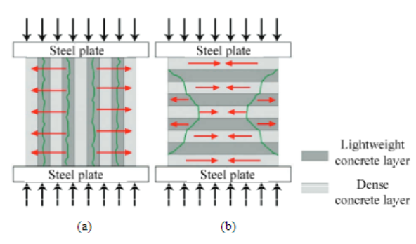
Fig. 22 Cracking behavior in concrete curves is composed of a mix of lightweight and dense concrete layers, although the whole cube is continuous. The cracks in green are caused as a result of the tensile stress applied onto the concrete. In (a), the force is applied in parallel to the slabs, and the FGC crack first due to the indirectly caused tensile stress. In (b), the compressive force is perpendicular to the slabs (Toader et al., 2017).
As a result of the properties listed above, FGCs are ideal materials when trying to minimize weight and save materials. FGCs also can reduce damage when going against strong forces like car crashes or earthquakes by trapping them locally, much like how the sea urchin’s spine prevents the spread of cracks.
The sea urchin relies heavily on its spines to traverse the rocky surfaces in the sea, and to survive crushing bites from aquatic animals; it is not surprising that those crucial members have already adapted to its harsh environment.
Effects of Torsion
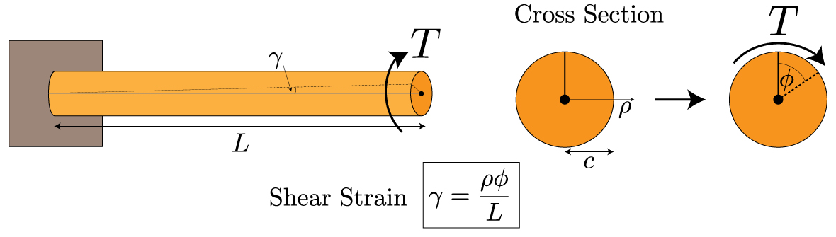
In contrast to compressive loads, sea urchin spines do not significantly rely on wedges for torsional loadings. Torsional stress is the stress of rotation on the spines. This could occur often, when these spines are attached to rocks, and the aggressive water flow in the regions they often populate, cause torsional forces. The spines must withstand this rotational force, or they risk being ripped apart. They do not depend on the same wedges discussed earlier. Instead, the bridges that connect the wedges in a circular fashion, take on most of the force. Indeed, if one were to twist a spine from both of its ends, then only the central backbone, the pores, and the bridges would be displaced as they are the only components oriented in a circular fashion (Tsafnat et al., 2012). One can determine that the farther something is from the center of a cylinder, the more strain it undergoes (Figure 23). This is examined using the formula for the shear strain in a cylinder due to a torsional loading :
The formula for the total strain, γ that a cylindrical object suffers under a torsional force. The strain is proportional to ⍴, the distance from the center of the cylinder, Φ is the angle the cylinder has been twisted, and L is the distance from the base of the cylinder (Holmes, 2019).

Fig. 23 T represents the torsion on the cylinder. The parts of the cylinder farthest from the center are far more strained than those at the center of the cylinder (Holmes, 2019).
Using Equation 2, the bridges, being the outermost cylindrical layer, undergo far more strain than the core of the spine. Hence, most of the torsional stress is appropriately distributed into the bridges between the wedges (Figure 24). If the spines did not contain any bridges, then the only support the wedges would have is their connection to the spine’s backbone, resulting in substantially less difficulty in twisting them off (Tsafnat et al., 2012). As observed with the wedges being effective relievers of tensile stress, the bridges are effective relievers of tensile stress. Without these stress absorbing microstructures, the spine would act like a simple bamboo rod which could easily be destroyed with torsional stress.
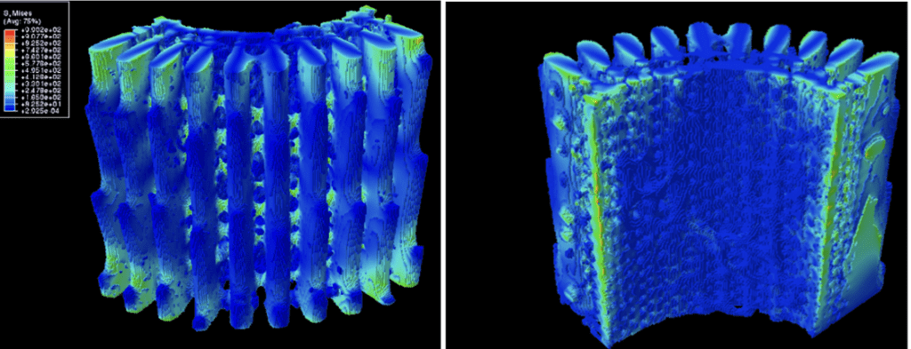
Fig. 24 Distribution of von Mises stress under torsional loading. All values in the legend are in MPa. The left image shows the outer surface of the spine while the right image shows the inner surface of the spine. Note that the left and right surfaces in the right image have some sections highlighted in bright green due to boundary conditions. An equal amount of torsion was applied in the opposite direction to prevent deformation (Tsafnat et al., 2012).
In essence, the hollow sea urchin’s spine is not a single cylinder but an assembly of several branches, columns, and pores that provide effective support under torsional or compressive stress. Furthermore, its abundance of pores ensures that the spines reach a peak weight-to-strength ratio. Most impressively, this naturally developed structure hides many functions that allow the sea urchin to thrive in the ocean almost entirely due to its spines.
Cactus Spines
Spines and their multifunctionality are not possessed solely by Animalia; species of plants have also adapted the structure and design of spines to aid in their survival. Succulents, pineapples, and blackthorn bushes all possess spines. Along with the previously mentioned species, the Cactaceae plant family possesses spines. Spines develop in cluster-like formations from the axillary buds of a cactus, and a leaf primordium (the initial formation of new plant growth) develops and swells. This growth is directed perpendicularly to the cladode, the flattened stem segments of the cactus. This shields the bud from herbivore predation with its protrusion (Mauseth et al., 2006). The second development stage consists of vacuolation and is more time intensive than the primordia stage. The spine’s cytoplasm content is increased. Spine primordia then develop on the axillary bud and protective guard cells also appear on the spine.
Fully formed spines, described from the base of a cactus stem, contain a basal segment with libriform fibers (LF) averaging 428 μm. These libriform fibers form a thicker secondary cell wall (Figure 25), further serving as a predation defense mechanism. These extend to the longer end barb fibers of an average of 576 μm length (Mausth et al., 1977). The length of the mature cactus spines ranges from a few millimeters to centimeters (Menezes et al., 2015). These lengths are much shorter than the respective lengths of 2-3 cm and 4-5 cm spines of hedgehogs and porcupines. The newly-formed spines do not have a visible cytoplasm, and in this regard, are considered to be dead (Mauseth et al., 1977). Mature spines also do not contain stomata, the controlled openings in plant cells reserved for the gas exchange of photosynthesis. This process solely occurs in the stem for the majority of Cactaceae species. This reduces the potential surface area for water evaporation and loss (Menezes et al., 2015).

Fig. 25 A near-mature spine cell. Stomata are absent due to a lack of photosynthesis within the spines. The gray outer segment of the cell is the thick wall that aids the spine with predation defense (Mauseth et al., 1977).
While both hedgehogs and Cacteae utilize their spines for defense, a functionality solely utilized by the latter is its mechanisms for increased water retention. Due to the habitat of cacti within harsh, often drought-prone environments such as deserts, they have evolved to maximize their water collection. Nopal cacti of the opuntia genus, have a spine density of 0.69 ± 0.03 g/cm3 (Marin-Bustamante et al., 2018). The cause of this low density is the hollow areas within the spine for nutrient transportation. The parallel alignment of denser libriform fibers covered with protective porous epidermal cells prevents dehydration of the spine, and this formation contributes to the structural strength necessary to deter predators (Figure 26) (Marin-Bustamante et al., 2018).
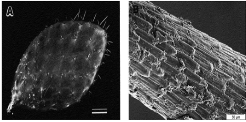
Fig. 26 The image of a cactus cladode with outwards protruding spines and an image of the alignment of cuticle cells. The epidermal cells are closely aligned to the spine, causing prevalent mechanical properties such as tensile strength, water condensation collection, and prevention of dehydration (Malainine et al., 2003).
Libriform fibers contain lignin, a protein that contributes to the strength of the spines. A higher lignin content correlates to a stronger spine and higher elastic modulus, or stiffness value. In a study on nopal cacti, the elastic modulus of libriform fibers in the transverse segments of the cacti spines was 20.75 ± 1.10a GPa (Marin-Bustamante et al., 2018). Segments of hardwood were only found to have a modulus between 16.9-24.6 GPa (Tze et al., 2007), and bamboo segments had a modulus value of 10.4-19.0 (Wu et al., 2009). Libriform fibers are three times as strong as epidermal tissue, which is attributed to their lignin composition of 24.6 ± 2.38% in cacti spines. The high lignin content in cacti spines causes them to have elastic modulus values comparable to hardwood (Marin-Bustamante et al., 2018).
The epidermal cells that cover the spine are corrugated for water retention and are not as dense as libriform fibers (Marin-Bustamante et al., 2018). The pores of the spine accumulate water from condensation along the plant (Figure 27, Figure 28). These pores and intracellular gaps provide cacti spines with a high surface area to volume ratio. Cacteae utilize their spine surface area in water-scarce environments to ensure maximum water retention and condensation (Eiseltova et al., 2012). As they do not contain stomata, cacti spines allow for water accumulation without any transpiration loss. These spine adaptations allow Cacteae to optimize water collection and storage for periods of drought.
Fig. 27 Images of the Nopal cactus. Libriform fibers (LF) and sclerified epidermis (SE) compose the tissue. The presence of the cell wall (CW), lumen (Lu), and intracellular space (IS) are indicated. Intracellular spaces further contribute to the porous structure and water retention (Marin-Bustamante et al., 2018).
The sclerified epidermal cells, or surface cuticle cells, also insulate the fibers from dehydration by forming a protective outer layer. The lumen and intercellular gaps work in conjunction to provide surface area and strength within epidermal cell walls (Malainine et al., 2003).
Fig. 28 Images of cacti species at the 300 μm scale. The parallel and porous alignment of libriform fibers along with the outer layer of sclerified epidermal cells contribute to spine strength and water retention (Malik et al., 2016).
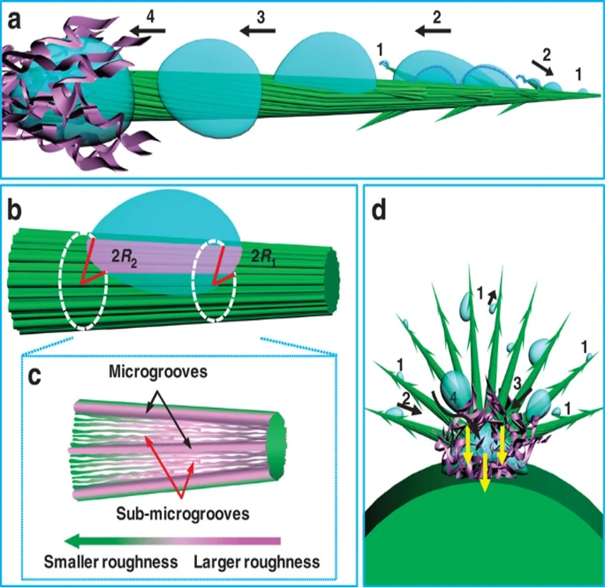
The Opuntia microdasys cactus has adapted its spines to maximize water collection, specifically from fog. Clusters of spines that range from 7 to 23 mm apart form, with some clusters containing up to 100 spines. The angle between spines was measured to be 18.1±5.3° and this assists the formation ofa hemispherical structure to maximize the volume of collected water (Ju et al., 2012). The epidermal cells of these spines span the middle segment of the structure and a barb forms at the tip of the spine. The parallel alignment of the epidermal cells represented by the green grooves in Figure 29 allows the water collected at the barb of the spine to move directionally to the base of the spine, where it can be collected into the water-containing mucilage cells of the cactus. Small hairs, or trichomes, at the base of the spine promote the absorption of water from the spine into the cacti. The upper epidermal cells are rougher than the lower epidermal cells of the spines. This drives a surface-free energy force that drives water to the hydrophilic mucilage. The base of the spine has a larger diameter, 65 μm, compared to the tip diameter of 30 μm. The larger radius of the base of the spine correlates to the change in Laplace pressure, which also provides a force that drives water to the base of the spine (Ju et al., 2012). These two forces drive the water to the collection, as shown in Figure 29. The equation for Laplace’s pressure gradient is shown in Equation 3.

Fig. 29 The roughness and Laplace pressure gradients resulting from increased spine radius drive water to be collected to the base of the spines with trichomes (Ju et al., 2012).

ΔP is the change in Laplace pressure, γ is the surface tension of water, α is the half apex angle of the conical spine, R0 is the drop radius, R is the local radius, and R1 and R2 are respectively the upper radii and lower radii of the spine. As R2 is greater than R1 , the Laplace pressure change will be negative moving towards the base of the spine and water will move towards the base of the spine with the pressure-generated force (Ju et al., 2012).
A research team utilized the water accumulation mechanism of the cactus to develop sweat-collecting sensors (Son et al., 2021). Sweat is a valuable bioanalytic data source in the human body; its effective collection would be less invasive than a blood test for patients. Sweat samples have been previously difficult to obtain for data analysis due to low and irregular secretion rates. The recently developed patch is in a wedge shape. The outer perimeter of the wedges is the most narrow, and the base of the patch wedges is the widest, mimicking cactus spines. The Laplace pressure force drives water from the tip of the cactus spine to its base. This force utilization was recreated in the biosensors, resulting in a spontaneous collection of sweat through the wedge microfluidic channels to the center of the patch (Figure 30). This collection does not require any external forces, as the force of the Laplace pressure overcomes any resistive forces acting on the sweat. The spine-inspired wedges laterally transport sweat to the sensor quickly and effectively (Son et al., 2021).

Fig. 30 The inspiration for the water collection of a cactus spine to the development of sweat collecting patch. The upper right image shows the force driven by Laplace pressure and the collection of water to the base of the cactus. Below the image of the cactus spines, are the wedges and channel for sweat collection. The bottom right image displays the movement of sweat from the outer segments of the sensor to the center, also driven by the Laplace pressure gradient. Over time the sweat moves to the center of the sensor (Son et al., 2021).
The spines of the cactus have been adapted to protect the plant from drought and maximize its environment. Their porous structure further assists with this collection as it maximizes surface area for condensation. The segments of epidermal cells in parallel alignment with denser libriform fibers along the spine contribute to the strength of the spine and provide the cacti protection from herbivores. These attributes also result in protection from dehydration and water loss. Cactus spines utilize forces caused by the pressure and roughness gradients of their spines to accumulate water. Spines offer mechanical aid to cacti comparable to that of animal spines.
Conclusion
How can porcupine spines be long enough to fend off predators from a distance, while also maintaining structural integrity as to not snap in two upon impact? These spines are not just hollow tubes, but rather porous microstructures filled with stiffeners which act like support beams, allowing the whole structure to resist all kinds of loads. As an added bonus, these spines detach easily upon contact, and thanks to their microbarbs, remain painfully embedded in the predator, often deterring future attacks on porcupines. Similar to porcupine spines, hedgehog spines also maintain stiffeners which act as excellent absorbers and prevent the buckling of the spine for hedgehogs who fall from high places often in search of food. This allows the animal to survive tumbles from various heights, and continue foraging without worry of any predators that may incite a vicious attack. For sea urchins, their fascinating environmental adaptation lies in the ability of the spines to protect them from the trashing waves in their environment. The unique microstructures and composition allows for them to withstand immense torsional and compressive forces by letting water pass easily through the spines and maintaining a similar internal structure of bridges. Lastly, cacti’s spines allow not only protection from any grazing, but also provide essential nutrient collection in a desolate environment.
References
Anderson, P. S. L., & LaBarbera, M. (2008). Functional consequences of tooth design: effects of blade shape on energetics of cutting. Journal of Experimental Biology, 211(22), 3619-3626. https://doi.org/10.1242/jeb.020586
Ben Salem-Fnayou, A., Zemni, H., Nefzaoui, A., & Ghorbel, A. (2014). Micromorphology of cactus-pear (Opuntia ficus-indica (L.) Mill) cladodes based on scanning microscopies. Micron, 56, 68-72. https://doi.org/10.1016/j.micron.2013.10.010
Byrne, M., & Andrew, N. L. (2020). Centrostephanus rodgersii and Centrostephanus tenuispinus. Developments in Aquaculture and Fisheries Science, 43, 379-396. https://doi.org/10.1016/B978-0-12-819570-3.00022-6
Cho, W. K., Ankrum, J. A., Guo, D., Chester, S. A., Yang, S. Y., Kashyap, A., Campbell, G. A., Wood, R. J., Rijal, R. K., Karnik, R., Langer, R., & Karp, J. M. (2012). Microstructured barbs on the North American porcupine quill enable easy tissue penetration and difficult removal. Proceedings of the National Academy of Sciences, 109(52), 21289-21294. https://doi.org/doi:10.1073/pnas.1216441109
Chou, S., & Overfelt, R. (2011). Tensile deformation and failure of North American porcupine quills. Materials Science and Engineering: C, 31(8), 1729-1736. https://doi.org/10.1016/j.msec.2011.08.002
Das, S., & Ghatak, A. (2011). Puncturing of soft gels with multi-tip needles. Journal of Materials Science, 46(9), 2895-2904. https://doi.org/10.1007/s10853-010-5164-2
Drol, C. J., Kennedy, E. B., Hsiung, B. K., Swift, N. B., & Tan, K. T. (2019). Bioinspirational understanding of flexural performance in hedgehog spines. Acta biomaterialia, 94, 553–564. https://doi.org/10.1016/j.actbio.2019.04.036
Eiseltova, M., Pokorny, J., Hesslerova, P., & Ripl, W. (2012). Evapotranspiration – A driving force in landscape sustainability. In Evapotranspiration – Remote Sensing and Modeling. InTech.
Gómez, C., Mira, J., Carrión-Vilches, F. J., & Cavas, F. (2021). Dynamic moduli of Polybutylene Terephthalate glass fiber reinforced in high-temperature environments. Materials, 14(3), 483. https://doi.org/10.3390/ma14030483
Holmes, D. (2019). Mechanics of Materials: Torsion. Boston University. https://www.bu.edu/moss/mechanics-of-materials-torsion/
Jensen, K. H., Knoblauch, J., Christensen, A. H., Haaning, K. S., & Park, K. (2020). Universal elastic mechanism for stinger design. Nature Physics, 16(10), 1074-1078. https://doi.org/10.1038/s41567-020-0930-9
Ju, J., Bai, H., Zheng, Y., Zhao, T., Fang, R., & Jiang, L. (2012). A multi-structural and multi-functional integrated fog collection system in cactus. Nature Communications, 3(1), 1247. https://doi.org/10.1038/ncomms2253
Karam, G. N., & Gibson, L. J. (1994). Biomimicking of animal quills and plant stems: natural cylindrical shells with foam cores. Materials Science and Engineering: C, 2(1), 113-132. https://doi.org/https://doi.org/10.1016/0928-4931(94)90039-6
Li, Y., Zhang, B., Niu, S., Zhang, Z., Song, W., Wang, Y., Zhang, S., Li, B., Mu, Z., Han, Z., & Ren, L. (2022). Porous morphology and graded materials endow hedgehog spines with impact resistance and structural stability. Acta biomaterialia, 147, 91–101. https://doi.org/10.1016/j.actbio.2022.05.027
Maier, F., & Bornemann, A. (1999). Comparison of the muscle fiber diameter and satellite cell frequency in human muscle biopsies. Muscle & Nerve, 22(5), 578-583. https://doi.org/https://doi.org/10.1002/(SICI)1097-4598(199905)22:5
Malik, F. T., Clement, R. M., Gethin, D. T., Kiernan, M., Goral, T., Griffiths, P., Beynon, D., & Parker, A. R. (2016). Hierarchical structures of cactus spines that aid in the directional movement of dew droplets. Philosophical Transactions. Series A, Mathematical, Physical, and Engineering Sciences, 374(2073), 20160110. https://doi.org/10.1098/rsta.2016.0110
Marin-Bustamante, M., Chanona-Pérez, J., Gυemes-Vera, N., Arzate-Vázquez, I., Perea-Flores, M., Mendoza-Pérez, J., Calderón-Domínguez, G., & Casarez-Santiago, R. (2018). Evaluation of physical, chemical, microstructural and micromechanical properties of nopal spines (Opuntia ficus-indica). Industrial Crops and Products, 123, 707-718. https://doi.org/10.1016/j.indcrop.2018.07.030
Mauseth, J. D. (2006). Structure-function relationships in highly modified shoots of cactaceae. Annals of Botany, 98(5), 901–926. https://doi.org/10.1093/aob/mcl133
Mauseth, J. D. (1977). Cytokinin- and Gibberellic Acid-Induced Effects on the Determination and Morphogenesis of Leaf Primordia in Opuntia polyacantha (Cactaceae). American Journal of Botany, 64(3), 337. https://doi.org/10.2307/2441977
Maxfield, B. (2009). Essential Mathcad for Engineering, Science and Math. 978-0-12-374783-9. https://doi.org/10.1016/B978-0-12-374783-9.X0001-X
Menezes, M. O. T., Taylor, N. P., Zappi, D. C., & Loiola, M. I. B. (2015). Spines and ribs of Pilosocereus arrabidae (Lem.) Byles & G.D. Rowley and allies (Cactaceae): Ecologic or genetic traits? Flora, 214, 44–49. https://doi.org/10.1016/j.flora.2015.05.008
Mori, M., & O’brien, S. E. (1997). Husbandry and medical management of African hedgehogs. ISU Veterinarian, 59, 5. https://dr.lib.iastate.edu/handle/20.500.12876/47778
Nickel, K. G., Klang, K., Lauer, C., & Buck, G. (2017). 13. Sea urchin spines as role models for biological design and integrative structures. In Highlights in Applied Mineralogy (pp. 273–284). De Gruyter. https://doi.org/10.1515/9783110497342-013
Piccinini, P., Alvarez-Sarandés, R., Trantallidi, M., & de Sertorio, M. (2011). Establishment of quantification methods for novel polypropylene/polyamide 6-based bicomponent fibre in textile binary mixtures. Textile Research Journal, 81(19), 1966-1976. https://doi.org/10.1177/0040517511402131
Roze, U. (2002). A Facilitated Release Mechanism for Quills of the North American Porcupine (Erethizon dorsatum). Journal of Mammalogy, 83(2), 381-385. http://www.jstor.org/stable/1383565
Seto, J., Ma, Y., Davis, S. A., Meldrum, F., Gourrier, A., Kim, Y.-Y., Schilde, U., Sztucki, M., Burghammer, M., Maltsev, S., Jäger, C., & Cölfen, H. (2012). Structure-property relationships of a biological mesocrystal in the adult sea urchin spine. Proceedings of the National Academy of Sciences, 109(10), 3699-3704. https://doi.org/10.1073/pnas.1109243109
Shergold, O. A., & Fleck, N. A. (2004). Mechanisms of deep penetration of soft solids, with application to the injection and wounding of skin. Proceedings. Mathematical, Physical, and Engineering Sciences, 460(2050), 3037–3058. https://doi.org/10.1098/rspa.2004.1315
Son, J., Bae, G. Y., Lee, S., Lee, G., Kim, S. W., Kim, D., Chung, S., & Cho, K. (2021). Cactus-spine-inspired sweat-collecting patch for fast and continuous monitoring of sweat. Advanced Materials, 33(40), 2102740. https://doi.org/10.1002/adma.202102740
Swift, N. B., Hsiung, B. K., Kennedy, E. B., & Tan, K. T. (2016). Dynamic impact testing of hedgehog spines using a dual-arm crash pendulum. Journal of the mechanical behavior of biomedical materials, 61, 271–282. https://doi.org/10.1016/j.jmbbm.2016.03.019
Tee, Y. L., Maconachie, T., Pille, P., Leary, M., Do, T., & Tran, P. (2021). From nature to additive manufacturing: Biomimicry of porcupine quill. Materials & Design, 210, 110041. https://doi.org/https://doi.org/10.1016/j.matdes.2021.110041
Toader, N., Sobek, W., & Nickel, K. G. (2017). Energy Absorption in Functionally Graded Concrete Bioinspired by Sea Urchin Spines. Journal of Bionic Engineering, 14(2), 369-378. https://doi.org/10.1016/S1672-6529(16)60405-5
Tsafnat, N., Fitz Gerald, J. D., Le, H. N., & Stachurski, Z. H. (2012). Micromechanics of sea urchin spines. PloS One, 7(9), e44140. https://doi.org/10.1371/journal.pone.0044140
Tuya, F., Martin, J. A., & Luque, A. (2004). Patterns of nocturnal movement of the long-spined sea urchin Diadema antillarum (Philippi) in Gran Canaria (the Canary Islands, central East Atlantic Ocean). Helgoland Marine Research, 58(1), 26-31. https://doi.org/10.1007/s10152-003-0164-0
Tze, W. T. Y., Wang, S., Rials, T. G., Pharr, G. M., & Kelley, S. S. (2007). Nanoindentation of wood cell walls: Continuous stiffness and hardness measurements. Composites. Part A, Applied Science and Manufacturing, 38(3), 945–953. https://doi.org/10.1016/j.compositesa.2006.06.018
Vincent, J. F. V. (2002). Survival of the cheapest. Materials Today, 5(12), 24-41. https://doi.org/10.1016/S1369-7021(02)01237-3
Vincent, J. F. V., & Owers, P. (1986). Mechanical design of hedgehog spines and porcupine quills. Journal of Zoology (London, England: 1987), 210(1), 55–75. https://doi.org/10.1111/j.1469-7998.1986.tb03620.x
Wu, Y., Wang, S., Zhou, D., Xing, C., & Zhang, Y. (2009). Use of nanoindentation and silviscan to determine the mechanical properties of 10 hardwood species. Wood and fiber science, 64-73. https://www.semanticscholar.org/paper/Use-of-Nanoindentation-and-Silviscan-to-Determine-Yan-Wang/fa73a68422795aab4f917a8395b531e4d5f5c151